
One of our favorite things about the competitive meets in our local league is what we learn about our robots and how they perform when it matters. Often when we practice, we are running one robot or at maximum two, but usually we’re not able to have four teams and a full field of game elements to simulate a real match experience. Different things seem to go wrong when it matters and points are on the line versus when we’re just practicing.
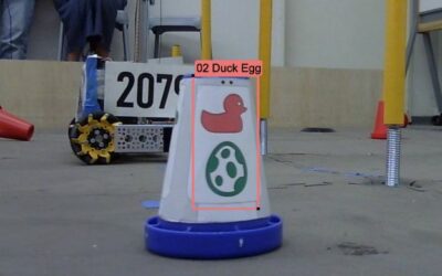
In Meet 0, for instance, we had an issue when one cone became trapped in the front of the robot, in the U-shaped area under the grabber claw. Because it was just one cone, some crafty driving was able to dislodge it. There was a risk of receiving a penalty for controlling more than one cone at a time when we had one trapped and the drive team was looking to pick up another cone with the claw to continue game play. We should’ve addressed this design challenge before Meet 1 but there were other priorities that put that on the backburner like getting the slides to all work reliably and improve our autonomous code!
During Meet 1 we had an instance where we wish we had solved this design challenge beforehand as Marvinette had two cones trapped in the front of the robot at one point which earned us a penalty for controlling two cones at once, plus, one of them belonged to the opposing alliance (which is not allowed!).
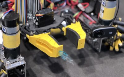
After we experienced this in Marvinette’s match, a few of the mentors starting discussing possible solutions in the pit area, beginning with a sketch and then taking a piece of cardboard from a pizza box and trimming a rough piece to quickly test the idea. Is seemed the concept had potential so one of the team members worked with a mentor to draft a 2D profile for the “scoop” and then laser cut it from cardboard for a test fit. The profile was drawn in Rhinoceros from dimensions taken from the actual robot. The test fit would allow us to see where we needed to create more tolerance or space between the chassis and other components.
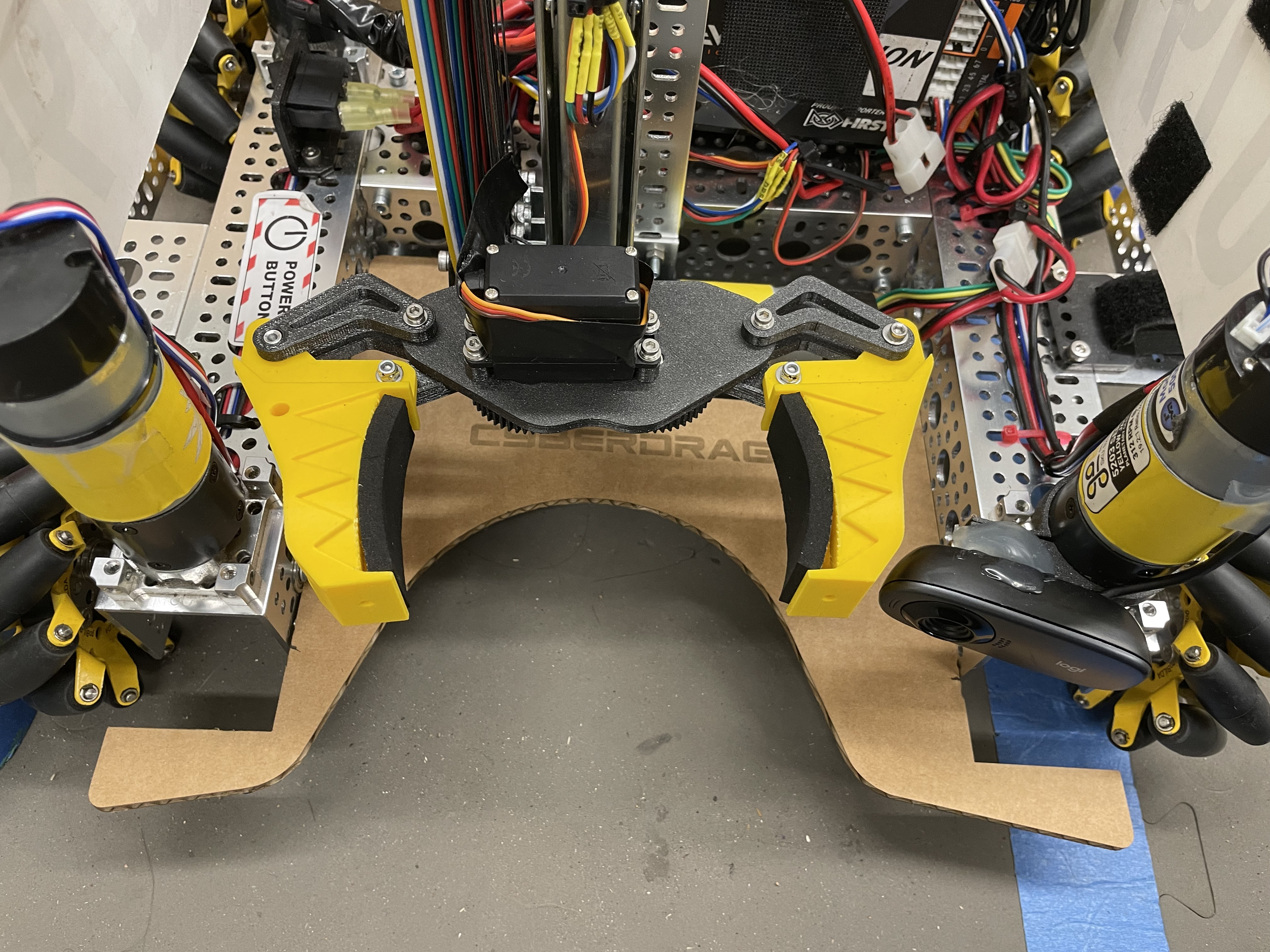
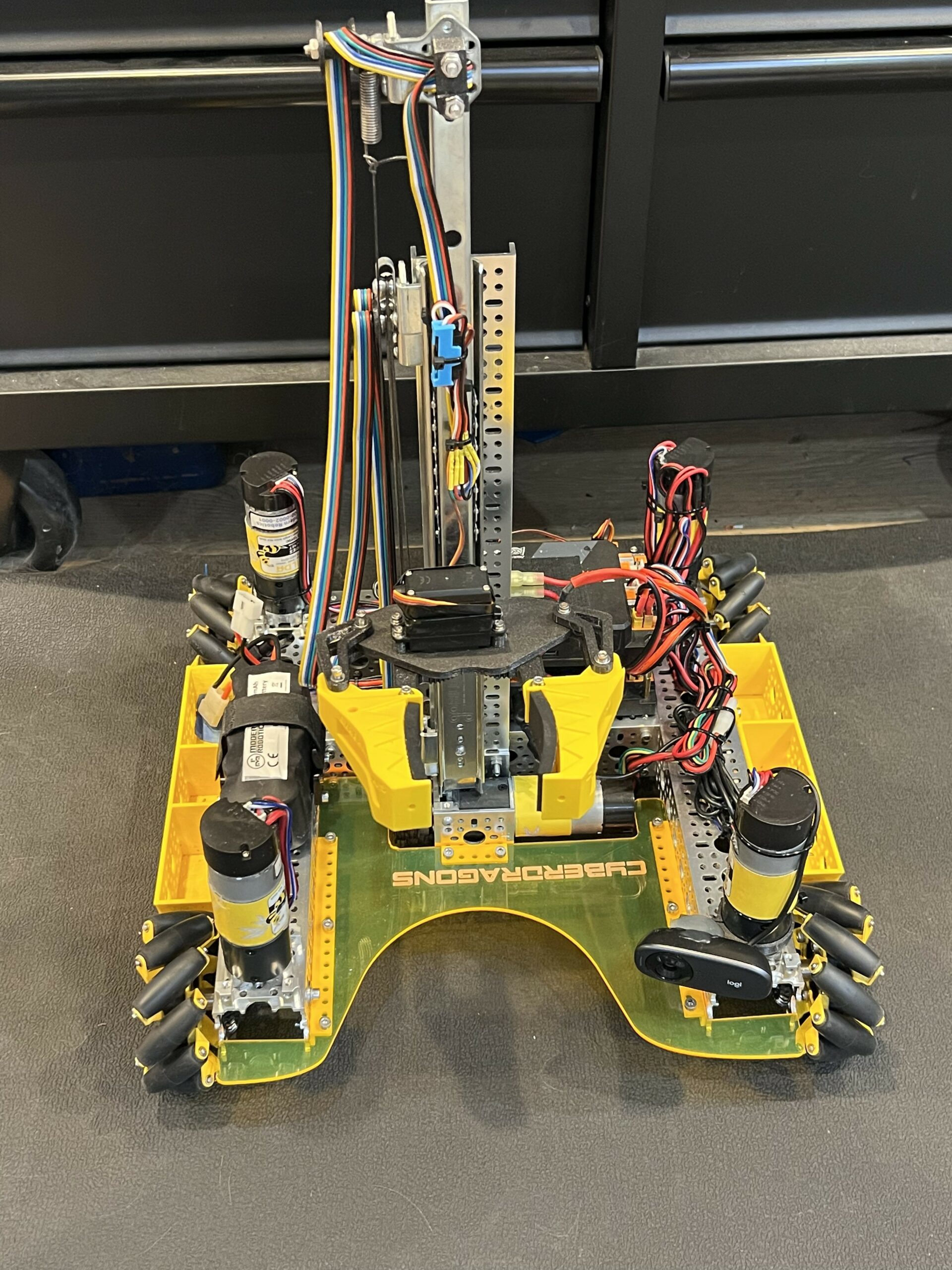
The image to the below shows the “U” chassis design where the claw drops down in front in the space that is created. The cones were becoming stuck in this area and the claw couldn’t be lowered all the way down.

Below are some images of the design and test fit process, going from sketch to cardboard prototype to laser cut acrylic part that was attached to the chassis and ready for testing! We’ll post videos of how well it’s working, or not, and any additional refinements that we make on our Youtube channel so be sure to check us out over there. Be sure to LIKE, SUBSCRIBE and smash the BELL to receive notifications of new content!
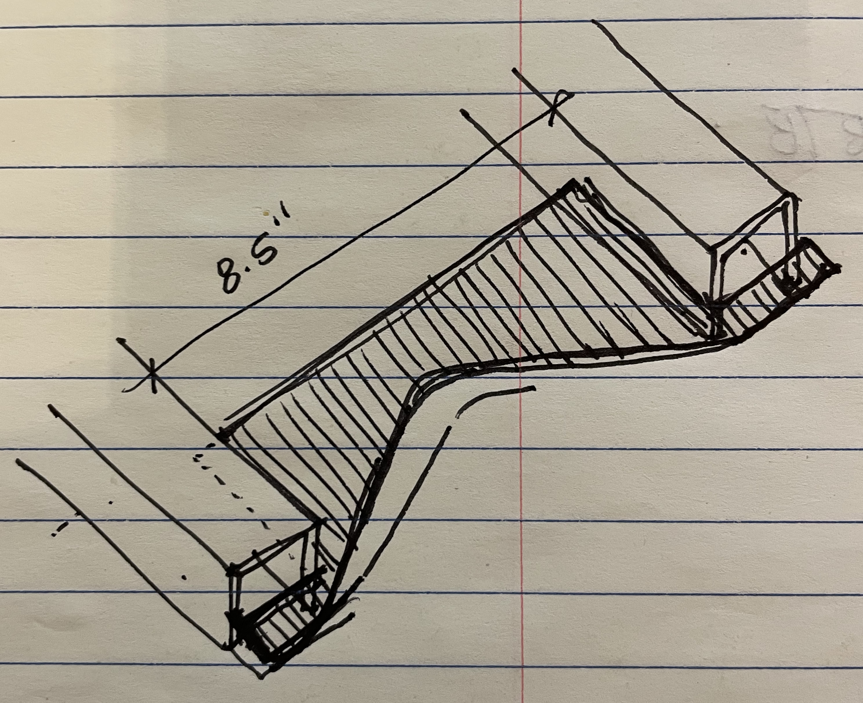
Quick Sketch Done in the Pit Area
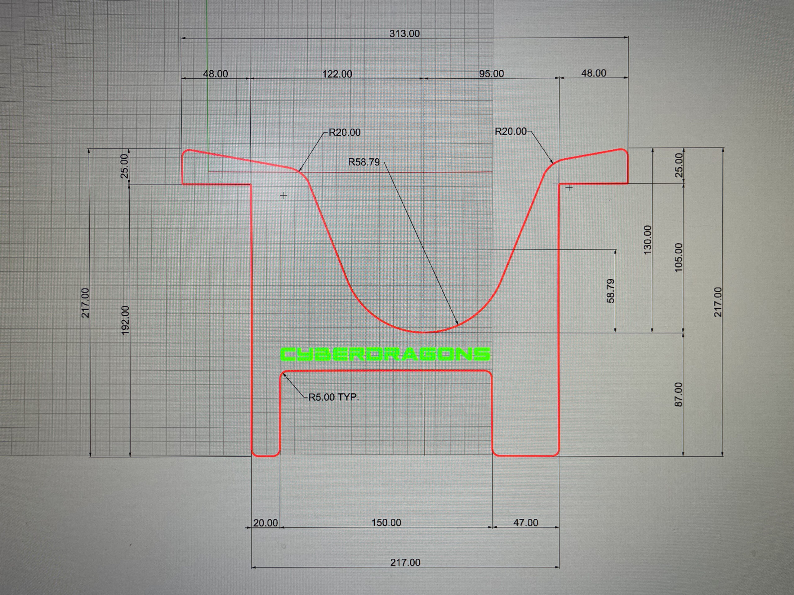
Screenshot of 2D Cut Profile in Rhinoceros
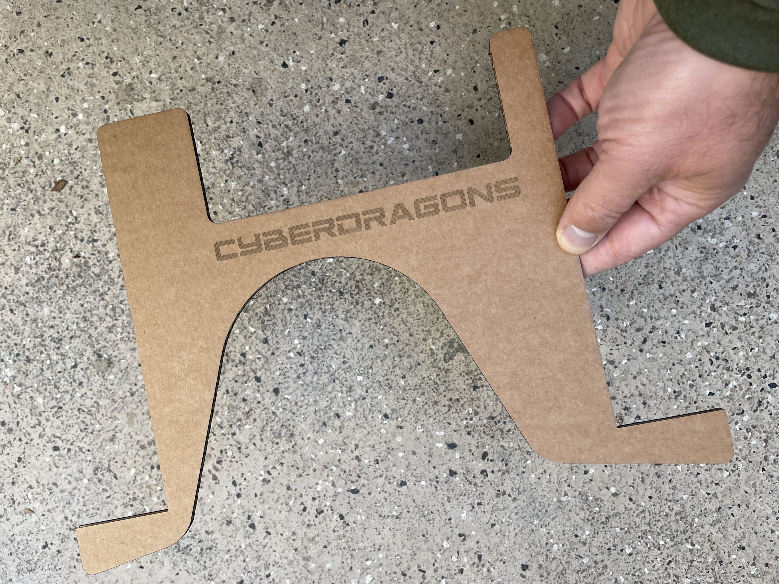
Cardboard Test Scoop
Test Fit of the Cardboard Prototype
Laser Cut Scoop Version1
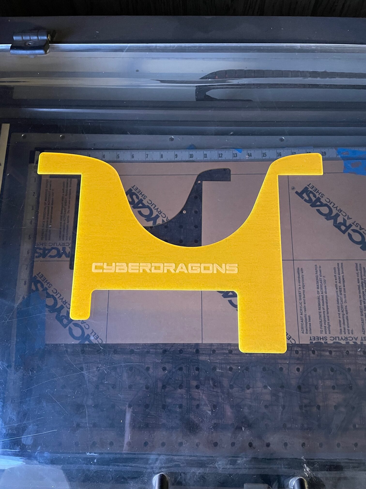
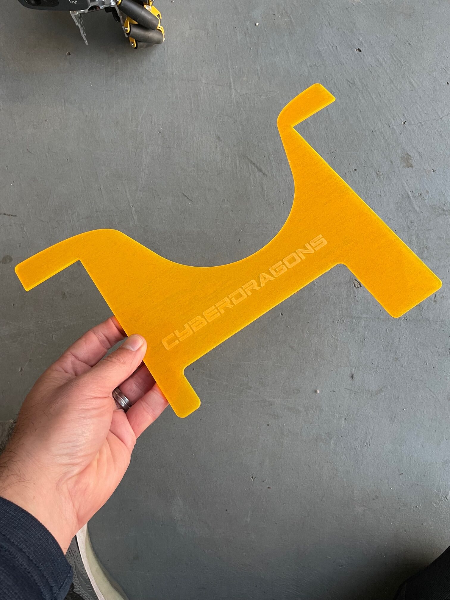
The Acrylic Scoop after Laser Cutting
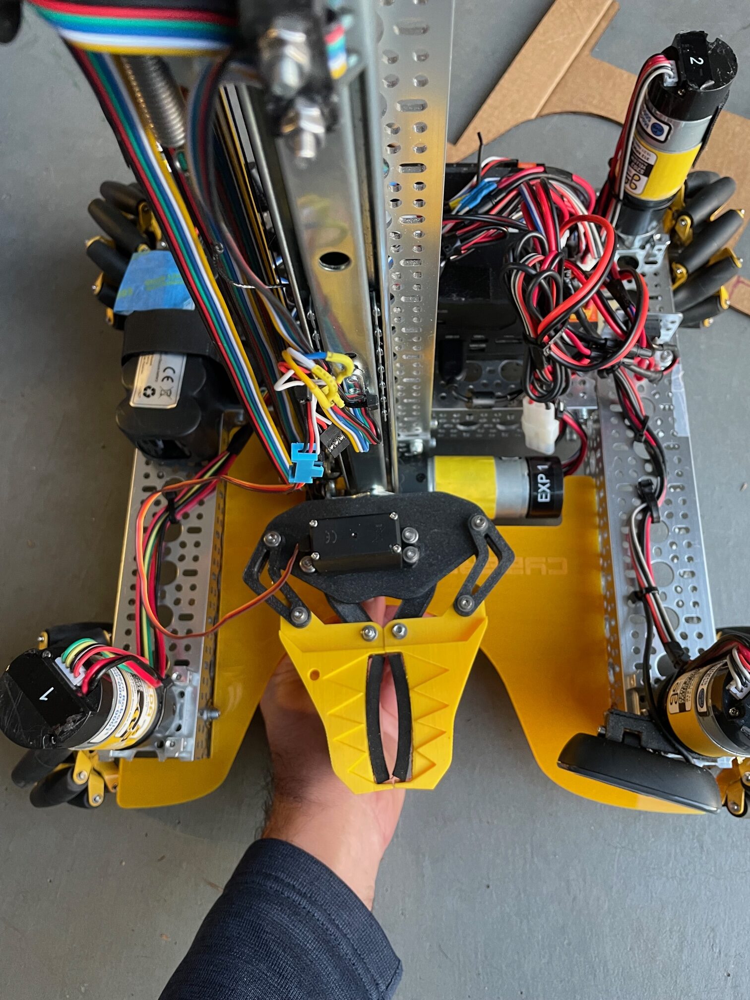
Test Fit of Final Acrylic Scoop
Finished Scoop Installed on King Bob
Watch our Youtube video short to learn more about the fabrication process:
0 Comments